Plastic Molding Polyethylene 03mm. Insert clean runners and scrap parts into the granulator throat.

Hitting The Numbers Part 1 Communication Is Key Plastics Technology
How well the parts.

. Dimension a numerical value expressed in appropriate units of measure and indicated on a drawing along with lines symbols and notes to define the sizegeometric characteristics of a part. Below are some suggested drawing notes to address this. We take a brief look at the most common types of plastics and how they are processed.
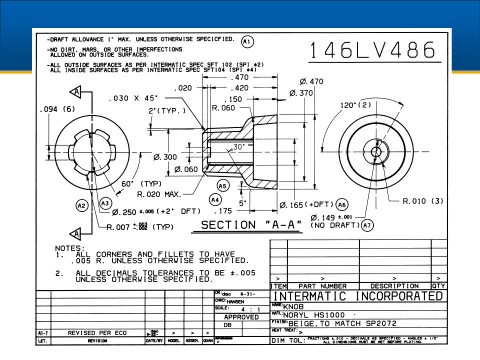
GW By Glenn Wilkins 033109. Plastic Part Drawings. A plastic part can have just a few dimensions or be fully dimensioned depending on your needs.
Above notes are meant to be added to or deleted as needed for the individual part or assembly drawing. Plastic parts can be made in many ways. Design part specification for plastic injection mold design 8.
COLOR MUST MATCH EXISTING XXXXXXX PARTS. Applicable Standards if any such as ASME Y145M - 1994 GDT. Is the Rockwell hardness in C scale for each component identified in the text box on injection mold print.
Producing Drawing A component or part drawing is termed as a production drawing if it facilities its manufacture. Designing plastic parts is a little different from designing metal parts. Machining drawings will contain all proper dimensions notes tolerances and.
Height of three times nominal wall thickness of part. The plastic parts about to join can be of same or dissimilar materials. A rib thickness of 60 to 80 of nominal wall thickness is recommended.
There are many things that must be carefully considered and planned for. Engineering Drawing Basic Sheet layout title Block Notes Engineering Working Drawings Basics. In Reply to.
Textual changes are not to be made other than as noted in Notes 6 7 8 11 18 21 and 22. Ive started a new job with a company whose products are injection molded. Coming from a world of steel and weldments this is kind of new to me.
It furnishes all dimensions limits and special finishing processes such as heat treatment grinding etc in addition to the material used. Is the Injection Mold Size LxWxH indicated on the plastic injec-tion mold drawing. Dont reach into the granulator throat.
The role of engineering drawings. You may also put information in there that is specific to injection molding like acceptable locations for parting lines and ejector pins and potentially even define where gates go to. Having a knurled ribbed or abraded surface on the metal part helps to ensure a strong permanent bond between metal and plastic so that the insert remains locked into the molded part.
Engineering graphics is used in the design process for visualization communication and. 51 Prototyping Plastic Parts 289 Figure 53 CNC machining of prototype plastic parts It can also be good practice to stress-relieve the blank or the workpiece at an intermediate stage of machining to relieve any internal extrusion or machining related stresses which could result in part dimensional changes over time or at elevated temperature. Injection molding thermoforming extrusion blow molding even.
Therefore knowledge about the influences that cause a failure is a prerequisite to develop a robust design and to prevent failures Shah 2007. It is an authorized document to produce the component in the shop floor. It tends to direct you to transmit the design information in 3D and then produce a control drawing with only the critical dimensions as well as the notes list.
EXTERIOR SURFACES TO HAVE A MOLD-TECH. Machined Parts Machined Part drawings which are probably the most popular of drawings needed. Joining of moulded plastic parts is required when the finished assembly is too large or complex to mould in one piece requires disassembly and reassembly is necessary and often to reduce cost to produce a single large moulded plastic component.
These are typical notes for molds we build both in house and out of house. Grind only one kind of plastic at a time. MOLDED FROM TRANSPARENT POLYCARBONATE PANTONE COLOR 2728C.
Wear eye protection in case plastic chips fly out. My question is what specific type of information is required in the NOTES section of an mechanical engineering drawing for plastic parts Generaly the following. Sadly most engineering drawings omit critical details about vendors.
All plastics are polymers. Appropriate dimensions to make the part and an understanding of the part tolerance for EDM and CNC set up. Part design rules Simple shapes to reduce tooling cost No undercuts etc.
INTERIOR SURFACES TO HAVE A SPISPE 3 FINISH. There usually is not a part that I cannot model and create drawings for. Plastic parts have had a bad reputation over the decades due to their characteristics that vary according to ambient conditions Tres 2000.
This question has a validated answer. Plastic Part Manufacture Injection Molding In the last 30 years plastics have become the most dominant engineering material for most products. 1Rib thickness should be less than wall thickness.
Dont hold onto the plastic push it in. Plastic is cheaper and easier to work with. Ive never seen drawings done the way they do it here and I would welcome your opinions on the following.
Are the tie bars for the press shown on injection mold drawings. The next time you are creating a silicone part drawing keep in mind that you should note Part must be free of flash in excess of 0010 or requirement number that works for your part design instead of the common Part must be free of burrs reference. These polymers are further divided into two basic types.
Your company standard policy is the best starting point look at your coworkers drawings and ask what they use. 2To increase stiffness increase the number of ribs or gusset plates another feature designed to strengthen the plastic part. Many devices have switched over to plastic parts.
They provide details on what is being built along with requirements for how it should be built and by whom. Draft angle to remove part In some cases small angles 14 will do Problem for gears Even wall thickness Minimum wall thickness 0025 in Avoid sharp corners Hide weld lines Holes may be molded 23 of the way through the. Molding in part inserts Inserts made of steel brass and aluminum components are commonly inserted into plastic parts during or after the molding process.
In the digital world engineering drawings are more important than ever. Engineering graphics is an effective way of communicating technical ideas and it is an essential tool in engineering design where most of the design process is graphically based. Posted byStephen G Martin on October 19 2002 at 145947.

Fabrication Drawings Ted S Engineering Drawing Blogs
20 Plastic Parts List Common Names And Abbreviations Used In The Manufacture Of Plastic Parts Explain The Difference Between Thermoplastic And Thermoset Ppt Download
2d Drawings For Injection Molded Parts R Askengineers

Hitting The Numbers Part 1 Communication Is Key Plastics Technology
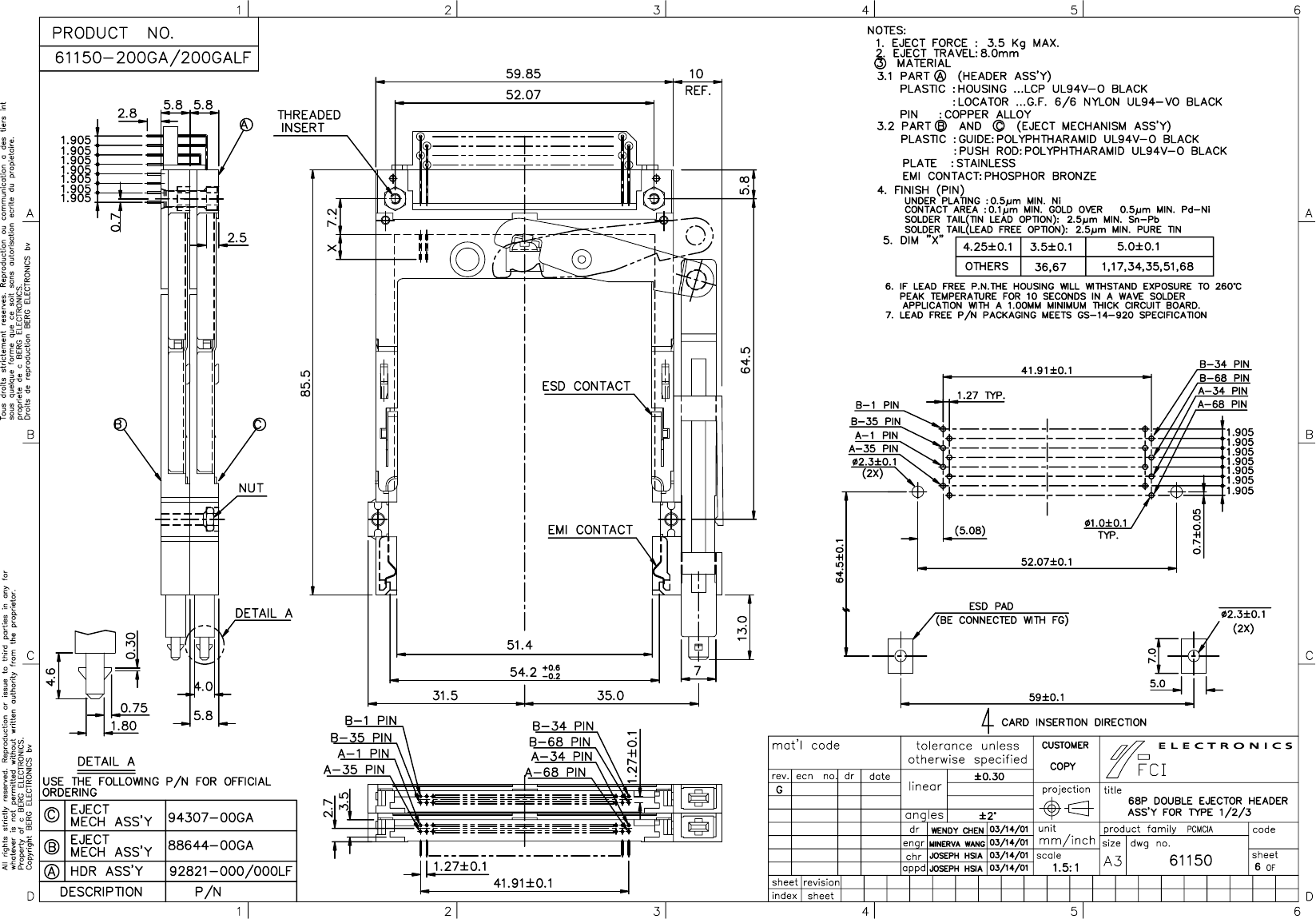
61150 Series Drawing Datasheet By Amphenol Icc Fci Digi Key Electronics

How To Make A Cnc Drawing Fictiv
How To Prepare A Technical Drawing For Cnc Machining Hubs

Line Drawings For Plastic Parts On Behance
0 comments
Post a Comment